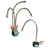
NH-M3 NH-M1

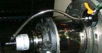
An example of NH-M1 usage |
[Application]
This holder is used to supply cutting fluid or air to machine tools. This
can also be used to remove chips and particles produced during electric
discharge machining by injecting cutting liquid.
[Features]
- Compared with conventional products, flexibility has been extremely improved.
The flexible part can be bent freely.
- Be employing a metallic flexible part, the holding posture is maintained
stably even when releasing high pressure air or a large amount of cutting
fluid. In addition, it is highly resistant to thermal damage by chips and
its durability has been improved.
- The powerful magnet enables the holder to be mounted in any position easily.
- The nozzle tip can be positioned in any posture and at any angle.
- The holder is equipped with a valve to enable adjustment of the flow rate.
|

NH-M1 Details of thread size |

NH-M3 Details of thread size |
|
| [mm(in)] |
| Model |
Holding Power |
Nominal Size |
Inlet Dia. |
Hose Length |
No. of Outlets |
Mass |
| NH-M1 |
245N(25kgf) |
φ70(2.75)×31(1.22) |
φ9(0.35) |
400(15.7) |
1 pc |
0.9kg/1.9lb |
| NH-M3 |
490N(50kgf) |
48(1.89)×73(2.87)×54(2.12) |
3pcs |
1.9kg/4.1lb |
※Upper li,it of pressure¥¥¥0.6 Mpa max. (Upper limit of flow rate: 10 litters/minute max.). However, depending on releasing angles, the posture of the hose may be changed by a jetting pressure even when the air/liquid pressure is below the upper limit. In such a case, turn the valve to reduce the flow rate.
※The holding power is based on a test piece of SS400, 10 mm thick, ground surface.
※The magnet section of NH-M and NH-P is common. Therefore the upper section is interchangeable for mounting between HN-M and NH-P.
※NH-M1, M3: Flexible part φ 11 mm |
|


